

Like any other electrical DIY project, setting up a solar system yourself can be a complicated process. To do it right, you have to devote a lot of time and forethought into how it will come together.
One very important step when constructing your own solar setup is putting together a solar panel wiring diagram (or schematic). This will essentially serve as your map as you connect all of your components.
Schematics is one of the more technical parts of DIY solar, but it doesn’t have to feel like rocket science.
In our guide, we unpack how to wire solar panels and provide diagrams illustrating solar schematic examples for every solar setup, from residential to RV to camper van. You’ll be ready to power up your home or get on the road in no time.
What Is a Solar Panel Wiring Diagram?
A solar panel wiring diagram (also known as a solar panel schematic) is a technical sketch detailing what equipment you need for a solar system as well as how everything should connect together.
There’s no such thing as a single correct diagram — several wiring configurations can produce the same result. It’s okay if your schematic looks a bit different from that of another solar DIYer, as long as everything is connected properly.
How to Design Your Own Solar Wiring Diagram
While you may be able to lean on existing wiring diagrams to build out your own system, there’s a chance you’ll want to design your own diagram. Below we outline how to do so, step by step.
1. Decide on a Medium
There are several ways to create your own solar panel wiring diagram — you can draw it out on paper, print out an existing diagram and mock it up with a pen to fit your liking, or design it from scratch digitally.
If you go the digital route, consider using a flexible tool that allows you to pull in images of your components from the web, such as Canva or PhotoShop. This will help make your diagram as realistic as possible.
While digital renderings tend to be higher quality and more true to reality than drawn-out diagrams, paper may give you more flexibility. Choose whichever medium suits your fancy, then move on to the next step!
2. Choose Your Components
Determining what components you’ll need and finding (or drawing) images to represent them will make your diagram come to life.
Most solar system setups will require the following standard components:
- Solar panels
- Inverter
- Battery
- Charge controller
- Cables and wires
If you’re working on a camper van or RV setup, you may also need to take into consideration some additional components that tend to already be built into homes, or that are unique to portable/vehicular solar. These components include:
- Fuse box
- Breaker
- DP switch
- Charger (or inverter/charger combo)
- Battery isolator
- Battery monitor
- Shunt
- Busbar
- Shore power plug
- 12v switches and outlets
3. Determine an Orientation
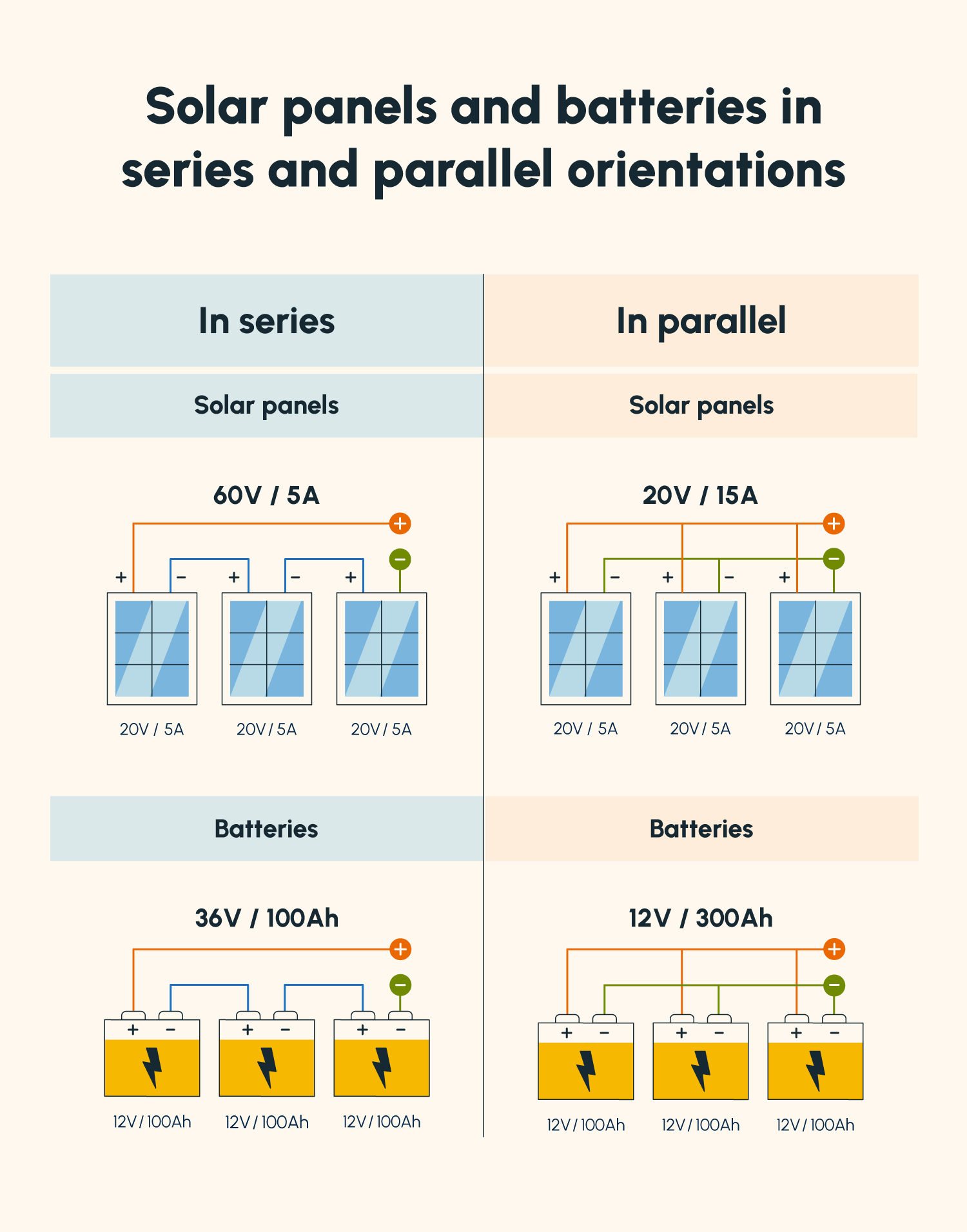
Solar panels and batteries can each be wired in one of two orientations: series or parallel. These orientations determine whether your devices’ amperage or voltage increases — an important consideration depending on what type of controller and batteries you’re using.
The orientation you choose will largely depend on the type of charge controller you use as well as the shading where you will be placing your panels.
Wiring Solar Panels and Batteries in Series
Wiring in series refers to connecting the plus of one panel or battery to the minus of another (+-). This adds the voltages of all panels together but leaves the current (amps) the same.
For example, if you have four panels wired in series, each with 20 volts and five amps, the output would be 80 volts and five amps.
Advantage
- Wire simplicity: With a low-amperage system (wired in series), you can use smaller-gauge wires, which are relatively inexpensive and easier to organize and manage. They can be more easily kept out of sight when running them from the panels to the other components of your solar system.
Disadvantages
- More expensive controller: When wiring panels in series, it’s necessary that you use a Maximum Power Point Tracking (MPPT) charge controller. This controller regulates high voltage to match that of a battery bank without resulting in power loss. However, MPPT controllers tend to be more expensive (by approximately $200) than Pulse Width Modulation (PWM) controllers.
- Only for unshaded conditions: Unshaded conditions are best for series wiring, as each panel’s performance in a series connection impacts the performance of the entire system.
Wiring Solar Panels and Batteries in Parallel
Wiring in parallel, on the other hand, refers to connecting two batteries’ or two panels’ pluses together (++) or minuses together (--). This adds the currents (amps) of all panels together but leaves the voltages the same.
For example, if you have four panels each with 20 volts and five amps wired in parallel, the output would be 20 volts and 20 amps.
Advantages
- Cheaper: As long as the voltage of your panels matches the voltage of your battery, you don’t need to worry about regulating your voltage when storing solar energy from parallel-wired panels in a battery. This is because your voltage doesn’t get added together when wiring in parallel. For this reason, you can use a less expensive PWM charge controller rather than investing in an MPPT controller.
- Independent output: With parallel wiring, each panel operates independently of the other panels in the system. This means that, if shade covers one or two panels, the remaining panels will continue to operate unimpeded by the shaded panels’ lower performance.
Disadvantage
- Wire management: The higher your amperage, the larger, more expensive, and less user-friendly your wires become. This may pose a challenge when it comes to organizing your wires from your roof and guiding them to your charge controller.
Wiring Solar Panels and Batteries in Series-Parallel
If you want to create more of a balance between volts and amps, you can also wire in series-parallel, which involves wiring panels together in series strings, then wiring those strings together in parallel.
For example, if you have four panels, each with 20 volts and five amps, you can wire each set of two together into a series string, then wire those two strings together in parallel. Add the volts of the two in series together and the amps of the two in parallel together to get your output: 40 volts and ten amps.
4. Draw Out Your Connections
After determining what components you need and deciding on an orientation for your panels and batteries, you’re ready to draw out your wiring diagram. Every line drawn between components should represent a wire.
Generally, your diagram should show wires leading from your panels to your charge controller. From there, they should lead to both your batteries and your inverter.
Since your inverter converts the current from direct current (DC) to alternating current (AC), making it usable for household appliances, wires should guide the current to your breaker, then to your appliances and outlets.
When connecting the components in your system in your diagram, remember to label everything. It’s also a good idea to color code which wires are connected to positive and negative outputs on your solar panels and batteries. In most diagrams, you’ll notice “plus” wires colored red and “minus” wires colored black.
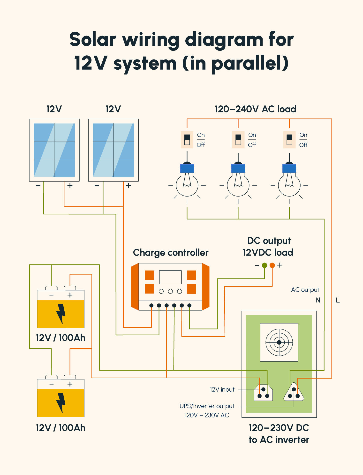
12V Solar Panel to Battery Wiring Diagram (in Parallel)
12V is the most common solar panel wiring connection with batteries, as most appliances are designed to operate on 12V.
With a 12V system, parallel orientation is usually preferred for both panels and batteries. This is because increasing the amps allows for devices to be powered for much longer than they could be when wired in series.
If you’re planning to wire a 12V system in parallel, download our solar panel wiring diagram PDF below.

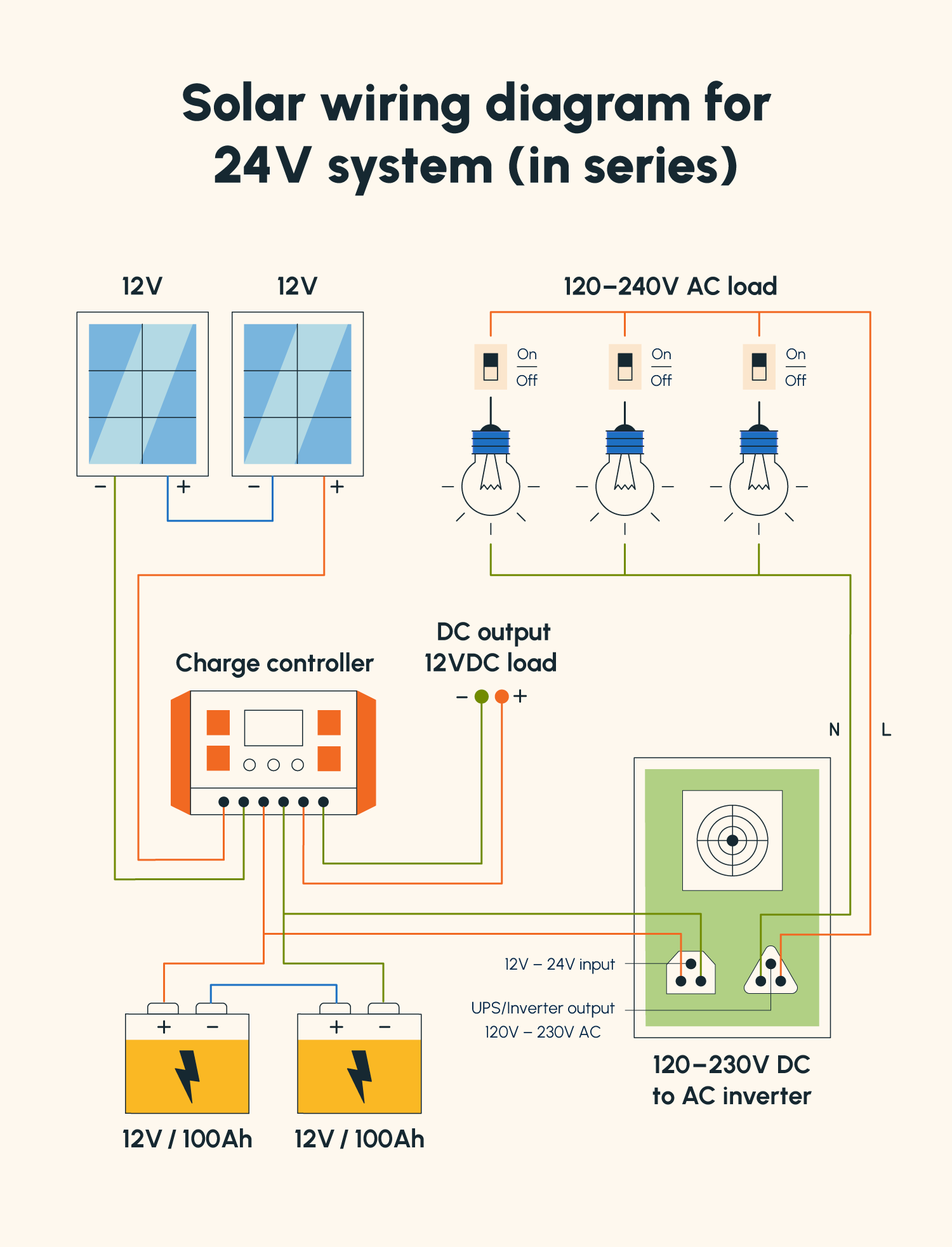
24V Solar Panel to Battery Wiring Diagram (in Series)
If you’re using a 24V battery bank and a 24V inverter, you’ll want to bring your solar panel voltage up to 24V as well.
This can be done either by using 24V solar panels and connecting them in parallel (since this leaves voltage alone) or by connecting sets of two 12V solar panels in series (since this will double the voltage to 24V) and everything else in parallel.
In the example diagram below, we demonstrate how this system can be mapped out by wiring 12V solar panels and batteries in series.

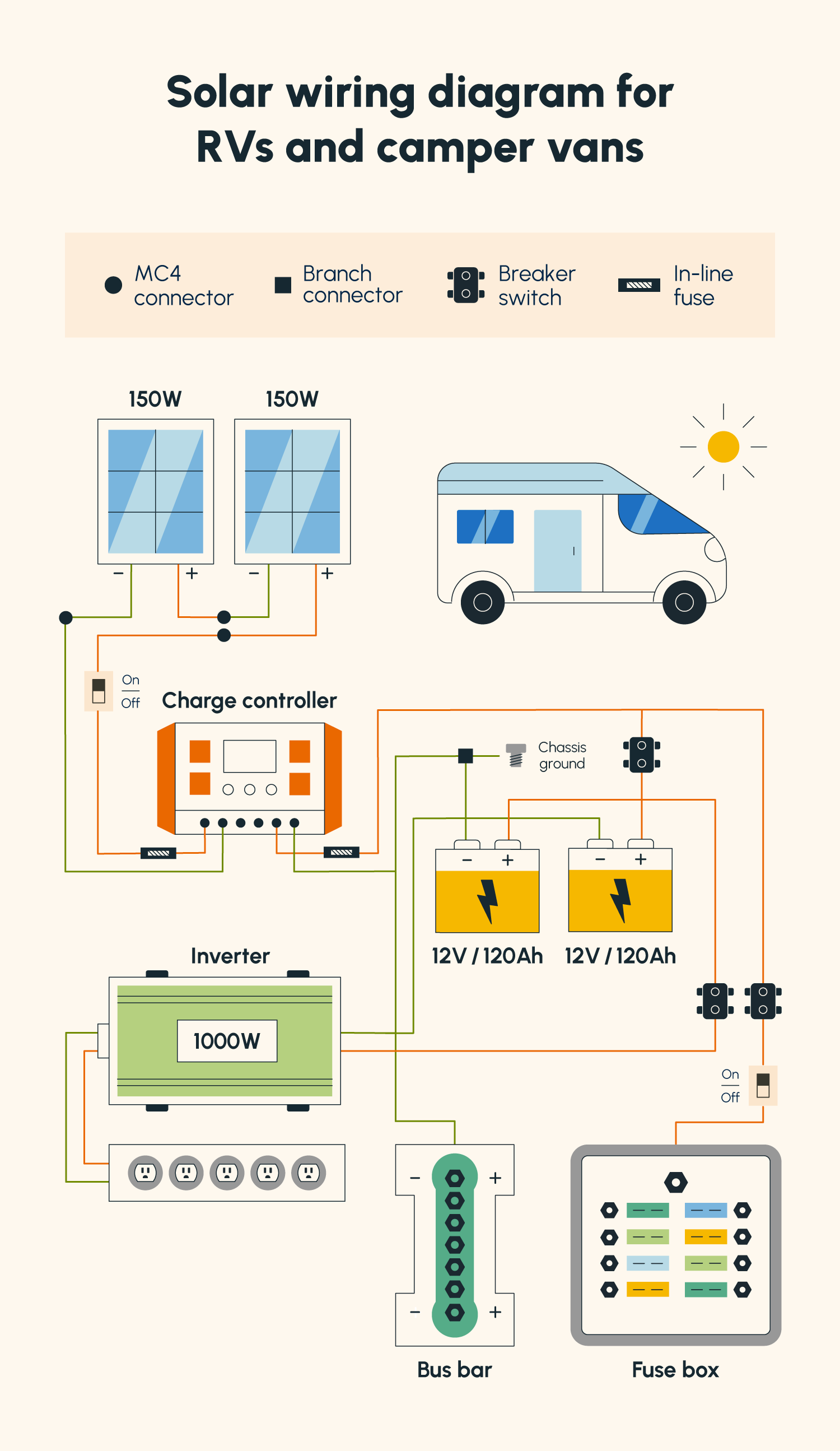
RV and Camper Van Solar Wiring Diagram
If you’re planning to set up solar in an RV or camper van and haven’t yet installed electrical components, there are a few additional parts you may have to factor in when creating a diagram of your system. These include fuses, a fuse box, and a busbar.
You may also consider investing in some brackets to keep your panels secured to the roof of your RV or camper van.
Download our solar panel wiring diagram PDF for RVs and camper vans below to help you plan out your system.

Solar Panel Schematic FAQ
Planning out solar system wiring tends to be one of the most complicated parts of a solar DIY project, especially since there isn't one right way to do it. Below, we answer some common questions about solar panel schematics.
How Do You Wire a Solar Panel System?
How you wire a solar system partially depends on whether you’re wiring your panels and batteries in series or in parallel (i.e., positive to negative vs. positive to positive).
Apart from the orientation of your solar panels and batteries, your solar panels should directly connect to your charge controller, as this is where voltage is regulated so that your panels can properly charge your batteries.
Wires should then run from your charge controller and split into your batteries and into your inverter. In the inverter, the current is converted from DC into AC, which then connects to your fuse box and provides power to your appliances.
What Wires Do I Need For Solar Panels?
The size of wires you need for solar panels depends on your system’s amperage and wattage. Fourteen-gauge solar wire can be used for some systems, but it can only handle a maximum of 15 amps. If your system will generate more amps, you should go thicker — probably around 10-12 gauges.
Residential solar systems usually work well with a wire between eight and 14 gauges. However, if you’re using a battery bank and charge controller, your wires should be much thicker — between three and eight gauges.
How Does Solar Connect to the Main Panel?
Solar panels connect to the main panel or breaker box through wire that first passes through the charge controller and the inverter. Once the inverter converts the current from DC to AC, the energy from the panels can enter the main breaker box and supply power to appliances.
Whether you downloaded one of our PDF examples or started creating your own solar panel wiring diagram, you’re officially on the road to become a solar DIY master.
Once you have your plan drawn out, be sure to check out our solar kits to get everything you need for your system delivered right to your door.


